![]()
![]()
![]()
![]()
![]()
![]()

Applications Engineering Notes
![]()
Failure Mode Analysis (FMA) Report on Excessive Heat Damaged White LEDs
Background:
On June 2003 a customer reported that they had experienced a total failure of 21 LEDs out of 90 installed on a prototype cluster board built with one of our standard 5 mm white LED through-hole parts.
The customer reported that some of the LED lamps, after the board was running ON continuously (24/7) for 2 weeks, had started to flicker and then soon after failed. It was also reported that excess heat was noticed. This excessive heat even caused Kester solder flux to run on the backside of the board. The customer installed the LEDs on the board by hand soldering method (low iron heat). The board is driven by a switching 12V power supply with 1% tolerance. The board is housed inside an aluminum extrusion with no internal air flow for cooling nor openings for ventilation. The 90 LEDs are connected in a circuit of 30 parallel branches of 3 LEDs in series with a 56-Ohm current limiting resistor in each circuit branch. The customer used the same value of resistor he used for driving LEDs from our leading competitor. The customer simply swapped the LEDs in the board. The customer stated that he had similar problems with the competitor�s parts (overheating, flickering and premature failure) although after a slightly longer period of continuous operating time. The customer saw that he had to increase the resistor value (from 47 Ohm to 51 Ohm to then 56 Ohm) to reduce excessive heat and subsequent early failure of the competitor�s LEDs.
Our engineering team received the prototype board. The board with the �bad� parts was sent for test and evaluation to determine the actual cause of the failures and thus the reason for this report.
Evaluation and Testing:
1. Upon first inspection, it was found that 9 circuit branches out of the 30 parallel branches had failed (27 LEDs not coming ON).
2. Only the first LED (of 3 in series) of each of the 9 non-working parallel branches was damaged thus opening the whole branch. The other 2 LEDs in the failed branches were in good operating condition.
3. Close inspection of the non-working LEDs revealed excessive heat damage to the die (the phosphor was black around the P-contact wire bond area). This is normally cause by excessively high drive Forward Current (IF) (probable current crowding).
4. The total current through the remaining 21 working branches was measured at 620mA. That works out to be 29.5mA through each LED.
5. The typical normal value of the Forward Voltage (VF) of our LEDs is between 3.0 Volts and 3.2 Volts. The VF of the remaining still working LEDs was between 3.5 V and 3.6 V. The excessively high IF through the LEDs had damaged these LEDs through a reversed vicious cycle, thus the total current through the circuit was now decreasing as the LEDs� VF increased.
6. Based on calculations using the nominal value of the current limiting resistors (56-Ohm) installed on the board and the normal VF (≈3.1 V) of our �good� LEDs, it is estimated that the LEDs were being driven at an IF of between 48 and 52 mA.
7. It was observed that the PCB board is of poor, or less than optimal, thermal management design. The PCB board utilized was for computer card type of applications rather than lighting applications. The copper circuit-tracing layer is imbedded (sandwiched) inside the FR4 epoxy/fiber glass laminate, instead of being on the completely or partially exposed to the outside, which will permit better heat dissipation through increased radiation and convection via airflow. The heat is being trapped and accumulating inside the board. See figures 1 and 2 below.
8. The current limiting resistors utilized were of low power rating (0.25 watt) and were placed on the same side as the LEDs and right next to the first LED of each branch, almost in contact. All of the damaged LEDs had two resistors next to them (on each side).
9. The heat inside and around the LEDs progressively increased due to the heat generated by the excessive IF and accumulated board and component heat which had no means of dissipation. There was no thermal differential to allow the heat to escape from the LEDs. The aluminum enclosure in which the board was placed was sealed with a front lens and had no openings for ventilation, thus no airflow inside.
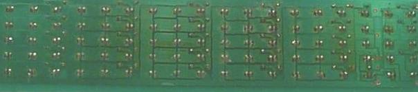
Fig 1. Back side of PCB. Copper circuit tracing imbedded epoxy/fiber laminate. Solder and Kester flux melted.
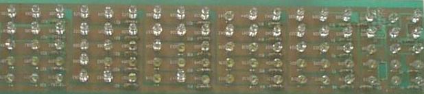
Fig 2. Front side of PCB. Copper circuit tracing imbedded epoxy/fiber laminate. LEDs sandwiched between resistors.
9. The total amount of electrical power running through the board, or being dissipated by the components alone, was calculated (based on all nominal values mentioned before) to be approximately 18 Watts. It is unknown (and unlikely) if the PCB utilized is rated for such power rating handling and dissipation.
10. The flickering observed on the LEDs was found in some cases to be caused by poor or weak soldering contacts between the board copper tracing and the LEDs� leads. As the heat builded up on the board, some soldering contacts debilitated, ran off, and even opened. The fact that the leads-holes in the board were slightly bigger than necessary exacerbated the problem. This phenomenon is common on board assembled by hand soldering. This leads to an �Open� in the circuit and thus dead (OFF) LEDs and/or complete circuit branches with LEDs in series.
11.
All completely and partially damaged LEDs were removed from
the board and replaced with new LEDs. Properly sized new resistors
were also installed (120 Ohm).
12. The proper resistance value was calculated using the actual VF of the LEDs (≈3.1 V) and the intended customer desired maximum IF of 25 mA (although 20 mA or less is recommended).
13. The board was then placed on continuous operation and placed under regular observation. To the date of this report (20 days later) none of the new installed LEDs have failed and the board is running at a stable current and temperature.
Conclusions of findings:
1. A combination of an excessively high forward drive current (IF) and the associated heat build up inside the LEDs and surrounding operating environment caused the accelerated aging and subsequent premature LED failures.
2. Improperly sized (ohm value) current limiting resistors had been installed (too small).
3. The resistors were placed next to, too close to, and surrounding the LEDs on each side (adding heat directly to the LEDs).
4. The customer incorrectly assumed or �thought� that the VF of our LEDs was equal to that of the competitor�s LEDs, thus installing our LEDs as direct replacement without checking the data sheets or making any direct measurements.
5. The PCB board utilized is thermally poorly or improperly designed, especially for the power load (and heat) is was being subjected to (≥ 18 Watts). It is likely that this board is designed for an application other that lighting.
6. The PCB�s copper tracing layer is embedded (sandwiched) and thus heat dissipation through radiation and convection is minimal to none. In addition, the aluminum enclosure has no openings for free air flow ventilation (as a minimum) nor a cooling fan (ideal). The board operates in an air insulated space.
7. Hand soldering of parts combined with the extreme heat build-up of the board contributed to LED flickering and the subsequent opening of the circuit paths in some of the branches.
Recommendations:
It is essential to completely understand the nature and characteristics of LEDs if one wants to assure their reliable long-term operation and/or push their operating limits. Not all LEDs are created equal. The Forward Voltage (VF) of LEDs varies not only from manufacturer to manufacturer but from batch to batch and even across each wafer. Therefore LEDs are commonly �binned� (sorted) by VF so that the end user can count in some degree of uniformity or �typical� value to make it easier for circuit design.
The white LEDs currently supplied by Brite-LED Optoelectronics have a typical VF range between 3.0 Volts and 3.2 Volts. So it is same to assume, for circuit design purposes, an average VF value of 3.1Volts.
This value is much lower than most other LEDs supplied by other vendors. Our lower VF can be considered as a good feature, since it translates into higher power efficiency (less volts consumed).
The luminous Intensity (Iv), or brightness, of a LEDs increases (somewhat linearly) as the LED is driven at a higher forward current (IF). Because of this �general� fact, users tend to like to �push� the LEDs to much higher currents above the recommended 20 mA. Although some immediate gain in brightness is obtained when this is done, this gain quickly becomes very counter productive. In principle, white LEDs loose efficiency as the power applied to them goes up. At one extreme, increasing the power by 7.5 times only yields 3 times the light output at the cost of a highly accelerating their output decay and life as well as increasing the risk of premature catastrophic failure. The culprit of all this is excessive HEAT buildup.
Under normal real-world conditions of use, which is the case of this application, the maximum current pushed through our white LEDs, or those from any other vendor with similar package configuration (through-hole 5 mm), should NEVER exceed 25 mA (under these duty conditions). Its is actually "very highly" recommended to stay at 20mA or less if all possible.
Based on the two observations and recommendations previously cited, the value of current limiting resistors to be utilized, in this particular circuit layout, should be NO less than 120 Ohms and ideally 150 Ohms or more. The higher it is, the lower the IF thorough the LEDs and thus the better the chances are for long-term component reliability, lower decay rate, and over all life expectancy.
Additionally, it is highly recommended that a better (properly thermally designed for the heat load and intended conditions of use) PCB board, outer enclosure (with openings for ventilation), and circuit layout (with heat dissipating components away from LEDs) be utilized for this application as well an automated DIP soldering process be adopted for the assembly of boards intended for resale and consumer use.
![]()
| HOME | PRODUCTS | ABOUT US | SALES | CONTACT US |TECHNICAL INFO |
copyright � 2002-2005 brite-led.com all rights reserved